|
Whitfield Trouble Shooting
This help file will help Diagnose most Whitfield pellet stoves.
The flow charts and are for Advantage II, II-T and plus stoves.
but the basic info will help with ALL pellet stoves.
Warning, this is
for your information only!
We do not assume any responsibility for the safety of your property or you.
Climate Control Systems are not the Manufacture of stoves.
We provide this help page From our years of experience for your information.
If you do not feel comfortable with electrical wiring nor have the proper tools
to test electrical parts CALL A
PROFESSIONAL!
go here for
Maintenance tips
Wire
diagrams
(large 3mg file has hand written notes)
Includes Pressure reading and auger times for most Whitfield stoves.
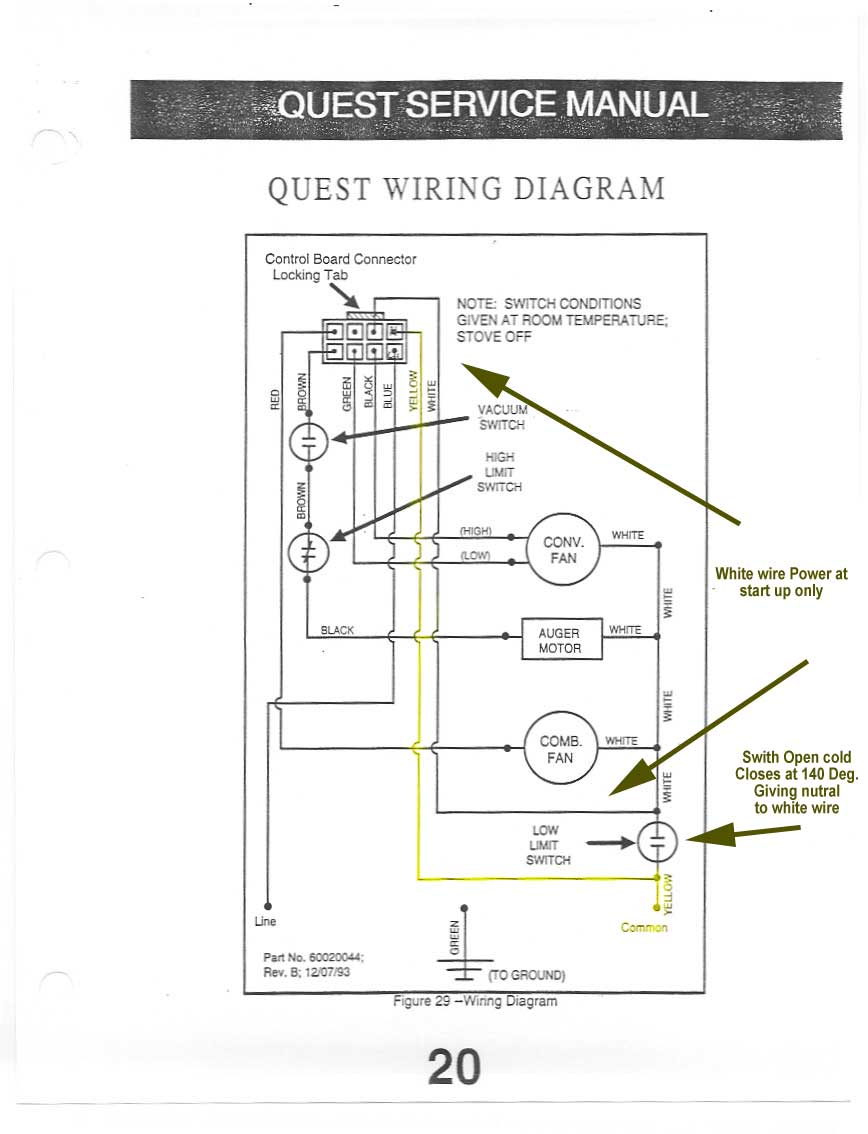
Quest only NOT
QUEST PLUS wire diagram and limit switch wires
The #1 reason a pellet stove will shut down after 10-20
minutes after start up is:
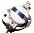
LOW LIMIT DISC PN 12057601
NOT used for Profile, Traditions or Optima Series stoves.
- Newer Lennox Units use a photo Eye to do the function of this switch if you
have a photo eye see this test
- Photo Eye
test PDF
Function:
To monitor the
temperature of exhaust gases and is designed to shut down the stove if it does
not sense the heat of the fire.
This switch is not electrically limited to any one system.
It is a surface mounted switch located on the “throat” of the
Combustion Blower housing. This normally “OPEN” switch is rated to close at 140
dg F (+ / - 6 dg). It resets to “OPEN” when temperatures drop below 110 dg F (+
/ - 5 dg).
NOTE: Power loss to the Fuel Feed System will only stop the
Auger Motor and pellet feed. The stoves Combustion and Room Air Blowers will
still receive power until an exhaust temperature reading below 110°F.
The Low Limit switch can fail either in the “OPEN” or “CLOSED”
position. Both failures have distinctive indications of failure.
♦
An
“OPEN”
failure is indicated by the inability of the stove
to run longer than 30 min. The control board timer completes its cycle but the
Low Limit switch fails to close when hot gases go undetected through the
Combustion Blower housing exhaust. The stove restarts with the push of the START
touch pad but shuts down again after 30 min.
♦
A
“CLOSED”
failure is indicated by the continuous fan operation
after the stove’s fire has gone out and the stove is cool. By removing the power
cord from the wall all fans stop but immediately start when the stove is plugged
back in.
Both failures require the replacement of the switch.
#1 reason auger motor will not operate is:
PRESSURE SWITCH
Function:
Monitors exhaust
movement out of the stove to determine if restriction to air flow exists.
Most times this system fails not because of the switch but
because the hose is broken or the Port the hose connects to to clogged at the
combustion blower.
Most times this system fails NOT because of the switch but because the hose
is broken or the Port the hose connects to the stove (NOT TO THE SWITCH) is
clogged at the combustion blower or where the port is located on your stove.
Some locations the hose is connect to are:
Combustion blower.
Back of the firebox
Ash pan
Ignitor tube
Intake air tube at the firebox

This switch has no electrical connection to the Combustion Blower system (IN
MOST STOVES).
The switch is normally “Closed” allowing the passage of electricity from the
control board to the auger motor. When a set amount of Negitive or positive
pressure (depending on stove) is detected, due to a restriction or blockage to
airflow, the diaphragm is moved to the “Open” position; power is cut to the
auger motor stopping fuel to the grate. If this condition occurs, inspection of
the stoves vent system is recommended. Some stoves the Ignitor circuit is also
connected to the vacuum switch.
First check to see of all Doors and Ash pan doors are latched tight and
getting a good seal.
Check that the flue is clean an clear of obstructions
Check that all ash traps are clean and clear
Check that your combustion blower is working
Electrically check the switch by disconnecting the brown and
white wires from the switch. Attach a voltmeter set for “continuity” detection.
The switch should show continuity (CLOSED) with the orange hose disconnected
from the Combustion Blower housing.
When the hose is connected back to the blower (power “ON”) if a
reading of “Open” is indicated, the vent needs inspection. With power “OFF” and
the hose disconnected, you can gently blow into the hose and cause the switch to
OPEN. When blowing into the hose stops, the switch should CLOSE.
This test indicates proper switch operation.
Some stove this could be just the opposite
depending if the hose is connect to a negative pressure area or positive
pressure area
If this switch fails or the hose
is bad, You can by-pass this switch by connecting the two wires together and
your stove will work normally.
HIGH LIMIT & INLET AIR SNAP SWITCHES
PN 12147705
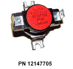
Function:
Surface mounted switches
that watch for excessive heat conditions. Both locations use the same switch.
Their mounting locations (see Service & Maintenance – Safety Switches) are based
on each switch’s responsibility of heat monitoring.
They are normally “Closed” switches.
These switches have no electrical connection
to the Combustion Blower system.
BLOWER HIGH LIMIT DISC - Monitors temperatures on the firebox
convection jacket and is designed to detect an over fire condition. It controls
power available to the Feed System. If tripped “Open” power is lost to the Feed
System. Inspection of the convection air paths, the blower voltage output
readings, the integrity of the blower motor and all wiring is recommended. All
ash collection points within the stove should be checked to remove any
obstructions.
INLET HIGH LIMIT DISC -Monitors temperatures below the
grate and in the inlet air path and is designed to detect reverse flow (caused
from negative pressure – tight houses which may not supply adequate combustion
and ventilation air.) It controls power available to the Feed System. If tripped
“Open” power is lost to the Feed System. Inspection of ash collection points
within the stove should be checked to remove any obstructions.
Check the switch for continuity. Apply heat to the bottom of the
switch and it will “Open”. Remove heat and it will “Close”.

Wire diagram for Advantage Series stoves with
Touch pad control board
Wire
diagrams
(large 3mg file has hand written notes)
Includes Pressure reading and auger times for most Whitfield stoves.
go here for
Maintenance tips
Whitfield Trouble Shooting
This help file will help Diagnose most Whitfield pellet stoves.
The flow charts and are for Advantage II, II-T and plus stoves.
but the basic info will help with ALL pellet stoves.
Warning, this is
for your information only!
We do not assume any responsibility for the safety of your property or you.
Climate Control Systems are not the Manufacture of stoves.
We provide this help page From our years of experience for your information.
If you do not feel comfortable with electrical wiring nor have the proper tools
to test electrical parts CALL A
PROFESSIONAL!
| 
 Parts Sales